Final Project
Part 1: 3D Modelling
When deciding on what to do for the final project, I knew I wanted to make some sort of lamp to decorate my room, but I wanted something that looks unique. I then came across these pictures and wanted to have my own go at it.
This is the modelling process I went through to design the lamp
One thing I learned when building this lamp was the create circle pattern feature which allowed me to duplicate the fins easily without having me to manually place each new fin. This feature saved me alot of time.
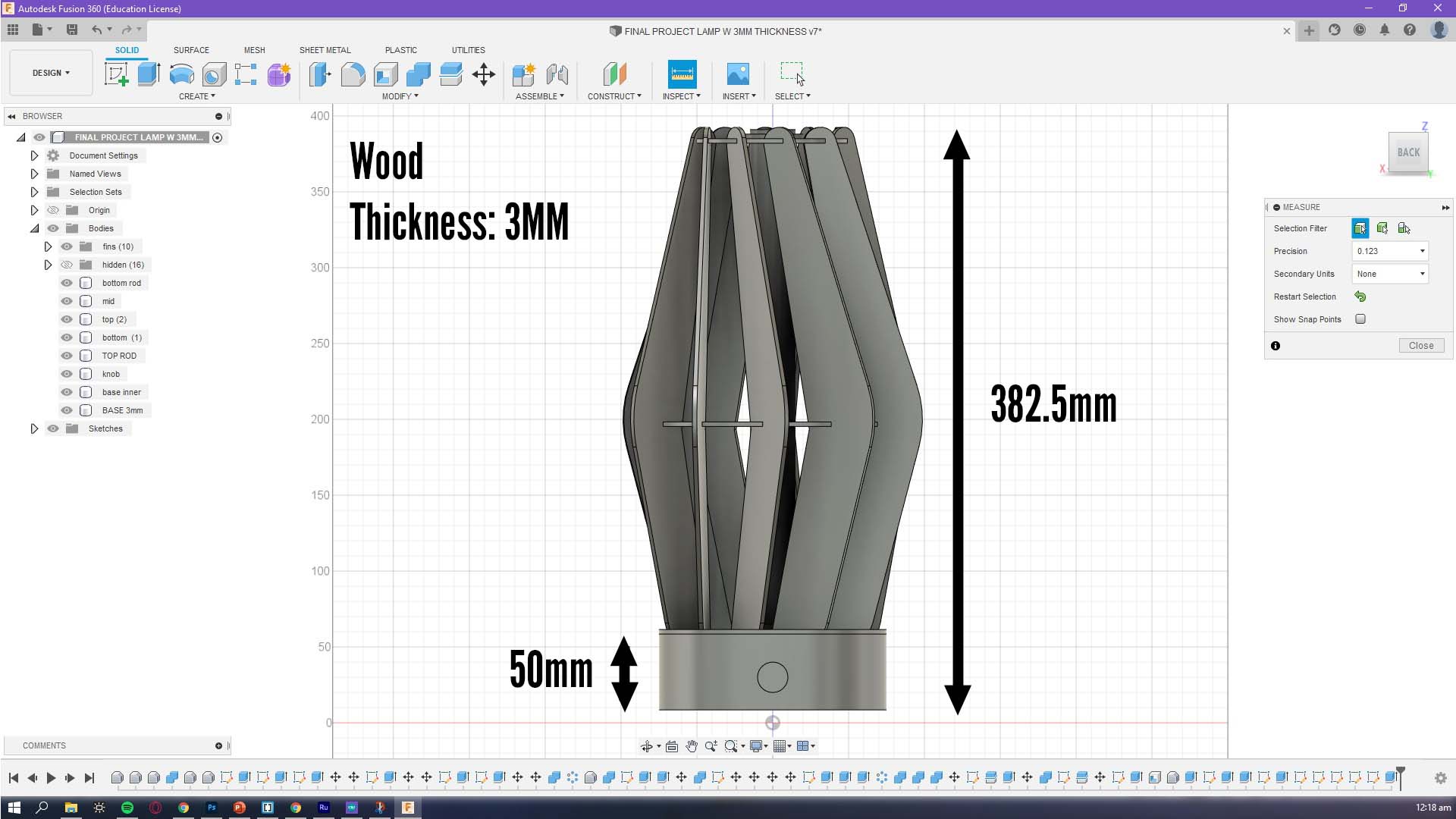
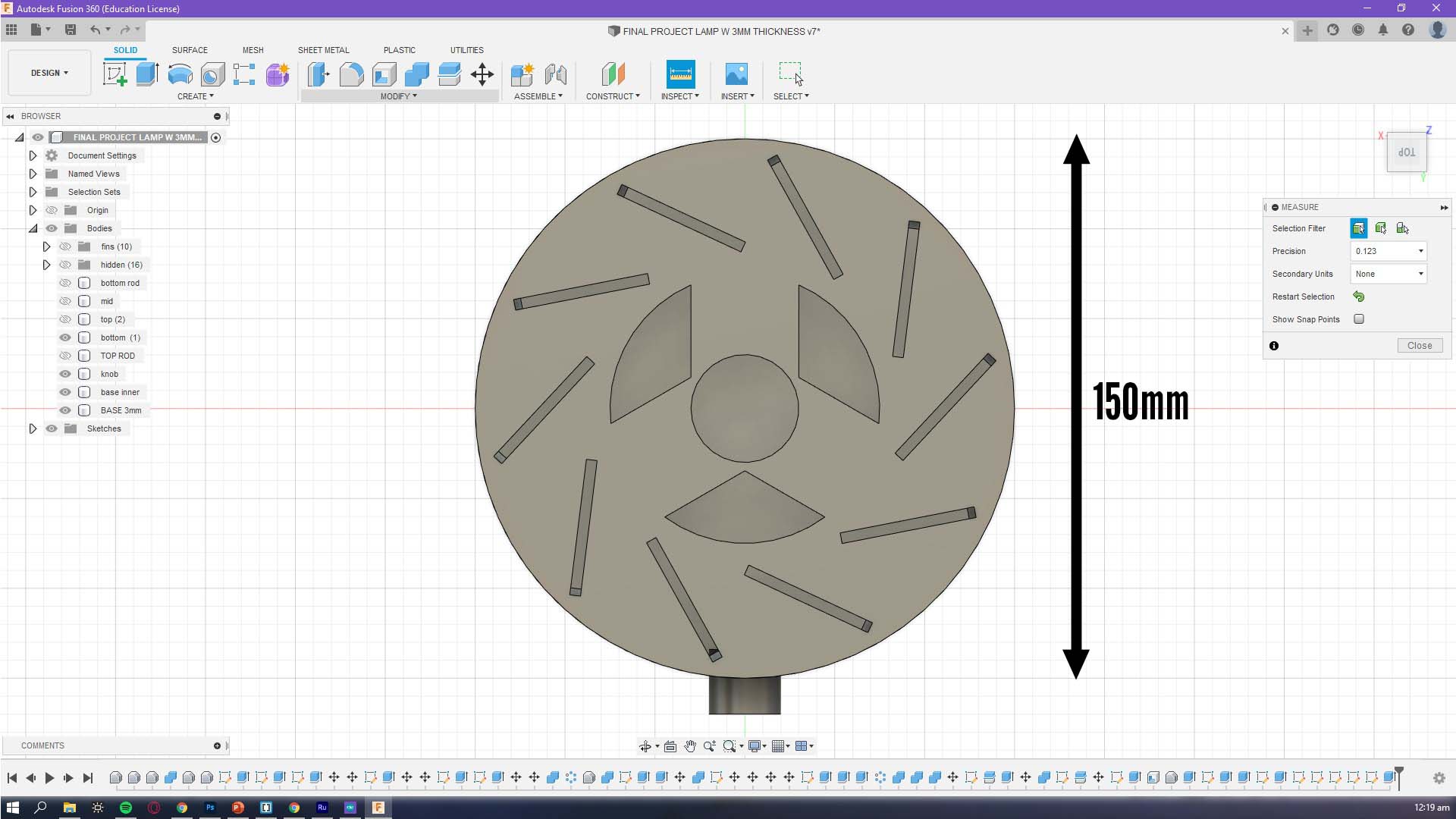
These are some measurements of the lamp
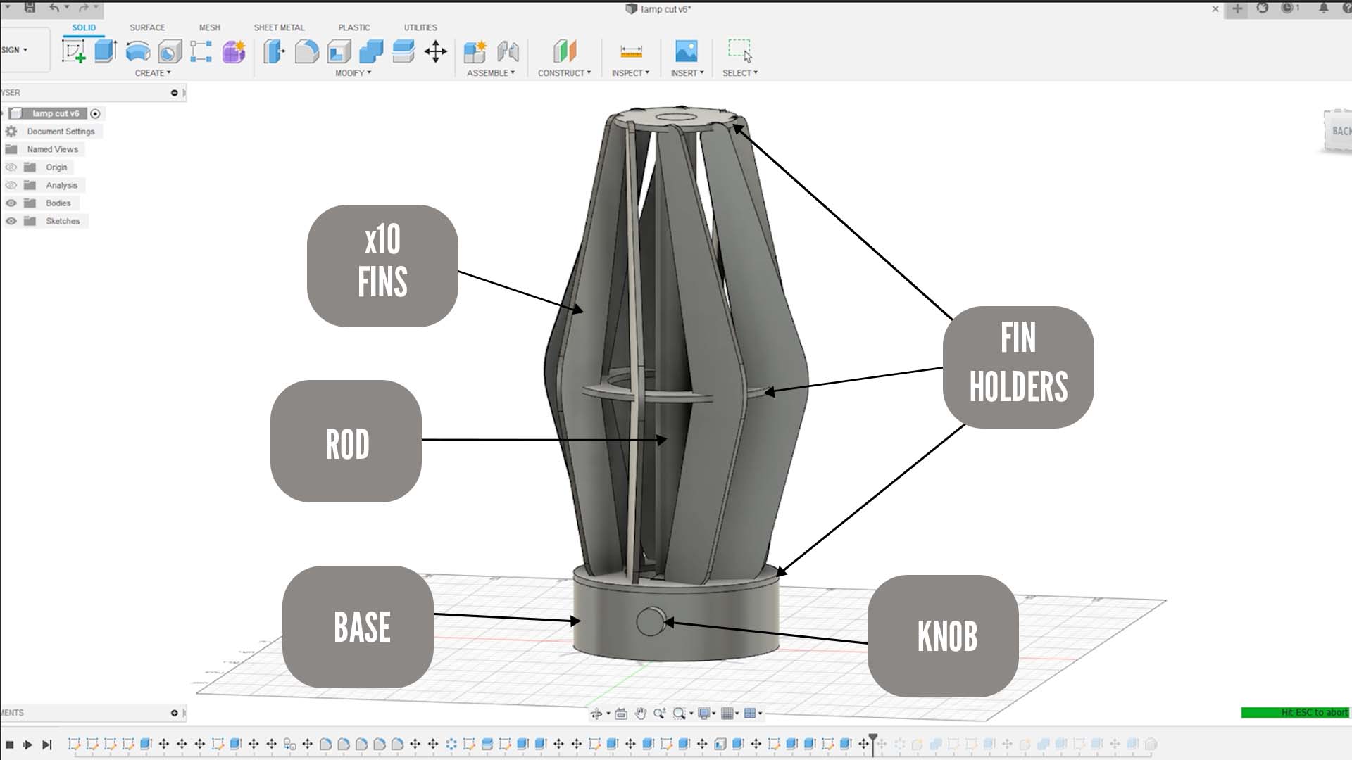
These are the key parts of the lamp
1. x10 FINS, used as a way to diffuse the light
2. FIN HOLDERS, located at the top mid and bottom of the lamp to ensure that the fins are secured
3. ROD, a way to hold up the lamp as well as to coil the neopixel leds around the lamp
4. BASE, store the arduino uno as well as the breadboard
5.KNOB, attached to a potentiometer to control the hue of the lamp
Part 2: Laser cutting and 3D Printing
3D printing of the base
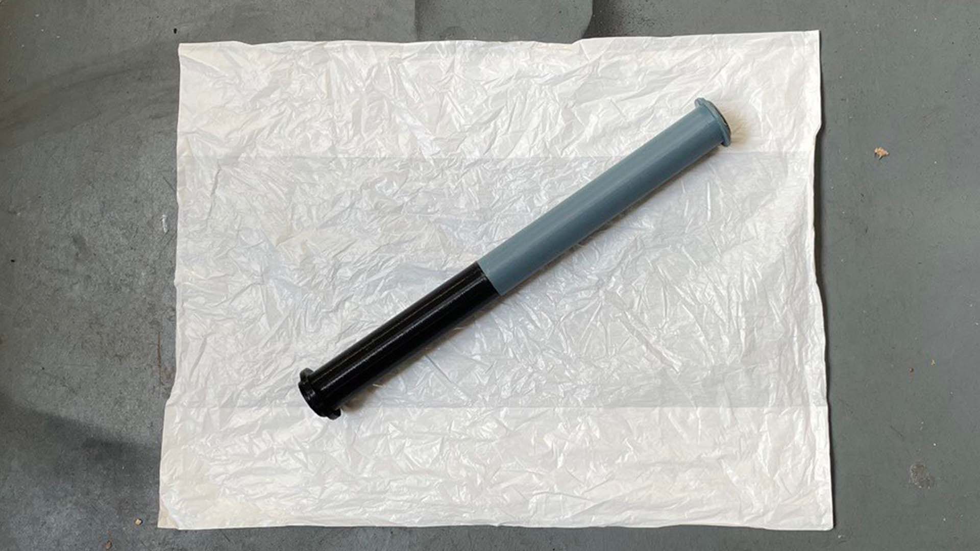
3D printing of the rod and the knob. The rod is printed in two parts as it does not fit inside the printer's build volume. The two knobs will be glued together later on
Laser cutting of the top mid and bottom fin holders
Lase cutting of the fins
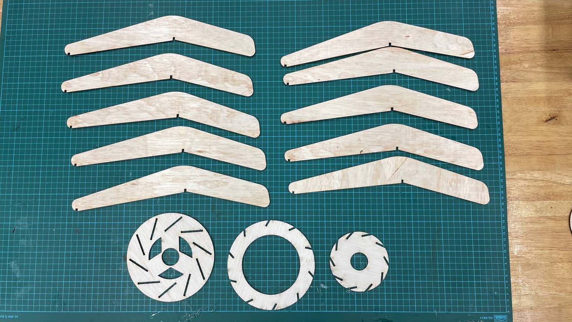
These are all the laser cut put parts
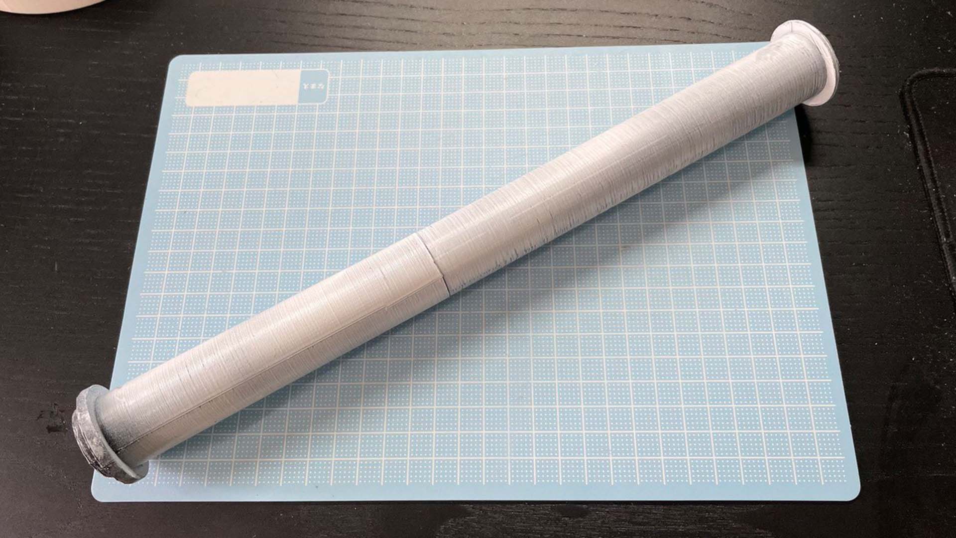
As previously mentioned, I glued together the 2 parts of the rod. Since the rods were printed in different colours, I decided to paint it white to give it a more consistent look. Whtie is also a good colour that would better diffuse and absorb the light.
Part 3: Electronics and Embedded programming
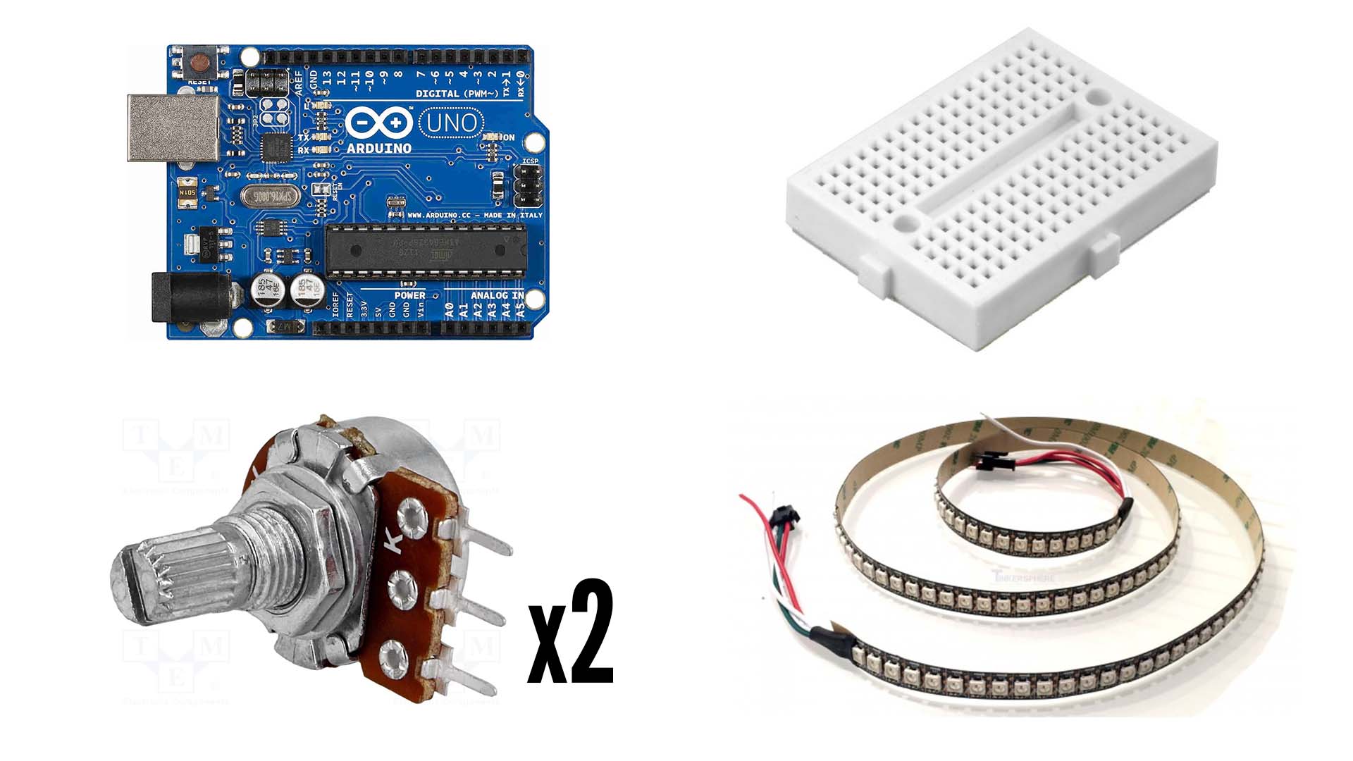
These are the electrical components I will be using
1. Arduino uno - Used as a microcontroller to communicate between the potentiometers and the leds
2. Mini Breadboard - Used to build circuits and connect components
3. 2 Potentiometers - Used as the input device. One will be used to control the hue of the led and one will be used to control the brightness led
4. 24 LED neopixel strip - Used as the output deivce
This is the code I used to control the lamp with annotations to explain the code. In summary, it lights up the entire LED strip and allows the brightness and hue to be changed by 2 potentiometers.
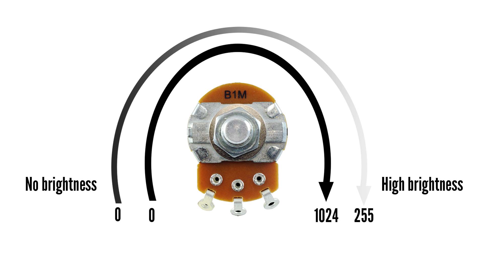
This diagram further explains the mapping of the potentiometer to the brightness. In the code above, the arduino can read 0-1024 analog values from the potentiometer. These values are mapped to the 0-255 values that is used for brightness. Therefore, as the potentiometer is turned, the brightness is increased.
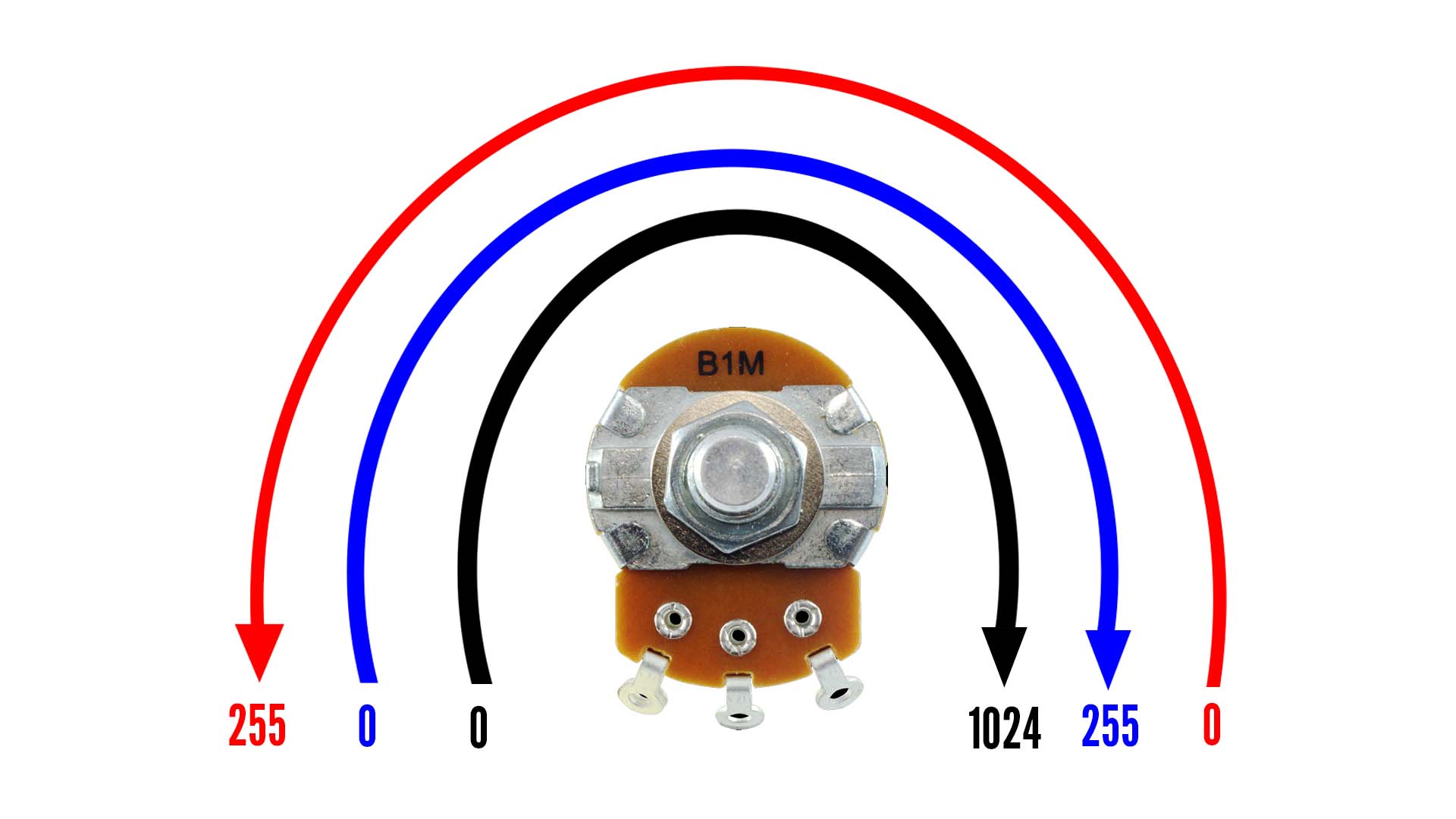
This diagram further explains the mapping of the potentiometer to the hue of the lamp. It is similar to the mapping for the brightness. Instead of brightness, I am mapping it to the red and blue values respectively. For the blue values it is mapped to 0-255 so that when the potentiometer is turned, it will go from zero blue to the highest blue level. As for the red values, it is instead mapped inversely from 255 to 0 so that when the potentiometer turns, it will go from the highest red level to zero red. By mapping these colours inversely, a greater range of colours can be achieved. So when the potentiometer is turned, it will go from pure blue to purple-like colours and all the way to pure red.
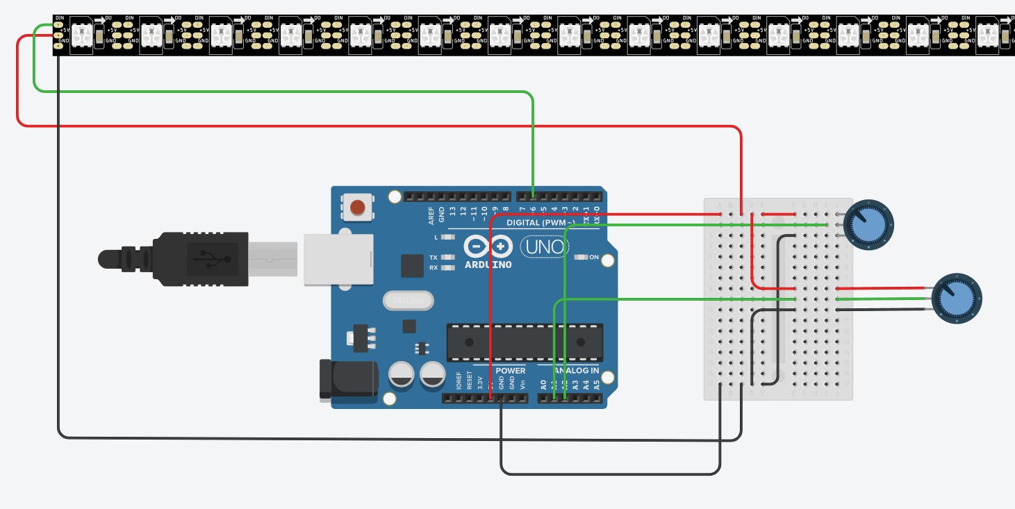
This is the circuit diagram. The potentiometer for colour is directly attached to the breadboard, while the other potentiometer, used for brightness is connected externally through wires so that it can be routed to the top of the base.
This is a demonstration of what the code does.
Part 4: Final Assembly and Demonstration
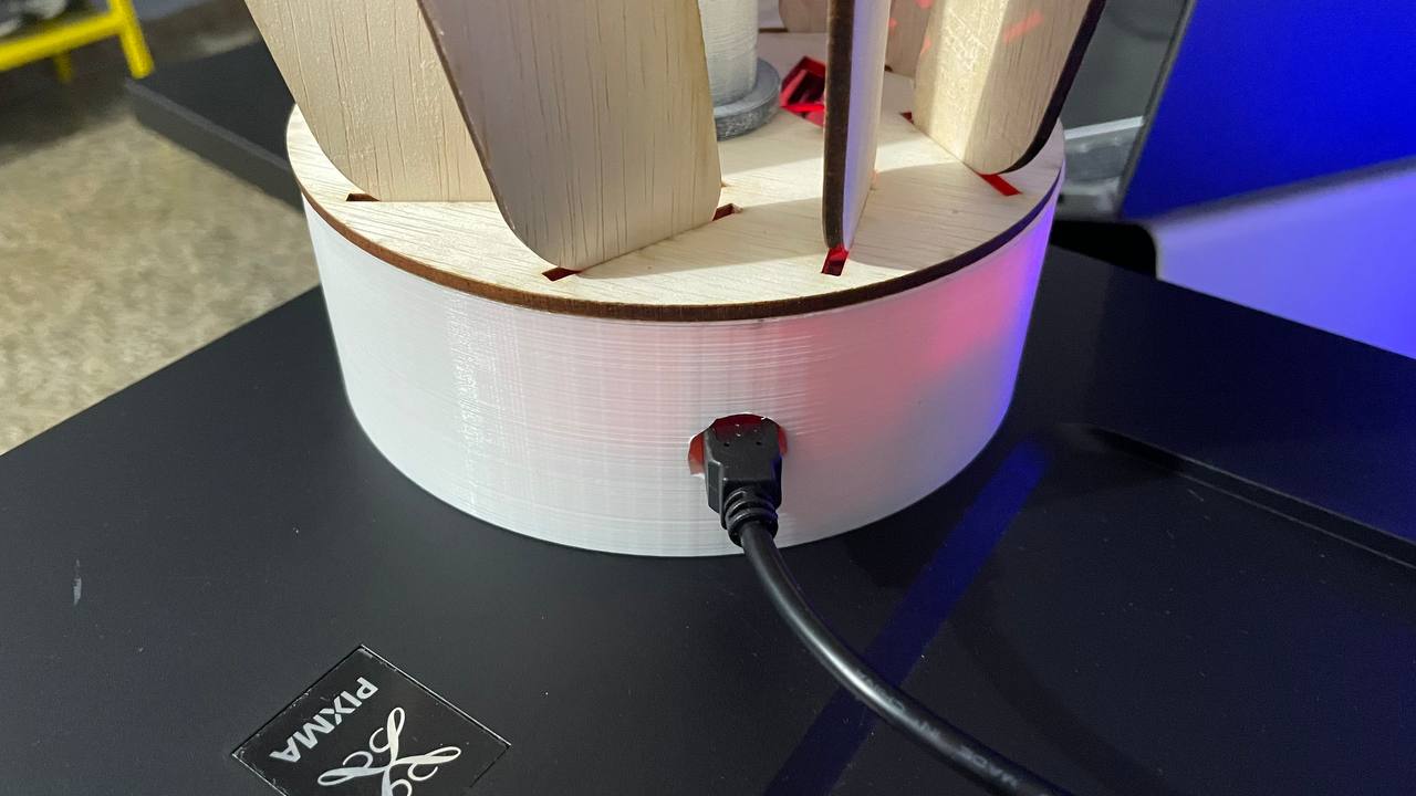
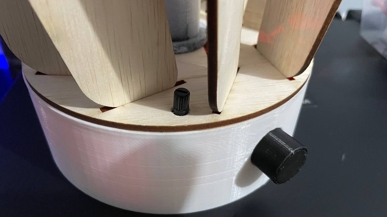
Before doing the final assembly, I actually had to make some modifications to the base as well as the bottom fin holder. In the first picture, I forgot to create another hole for the usb, so I used a drill to make one. In the second picture, I drilled a hole on the bottom fin holder so that I could fit the second potentiometer which is used to control the brightness. I had to do this as I did not intend to have this feature in the first place, but I was thankful that the modification went smoothly and did not damage my parts.
This is how the electronics fit in the base.
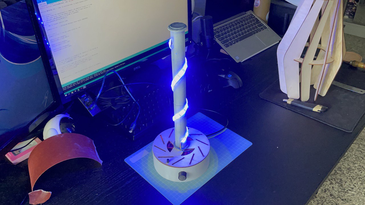
I first assembled the base as well as the rod and LEDs. The fins will then sit on top of the rod
This is the final timelaspe of the lamp being assembled
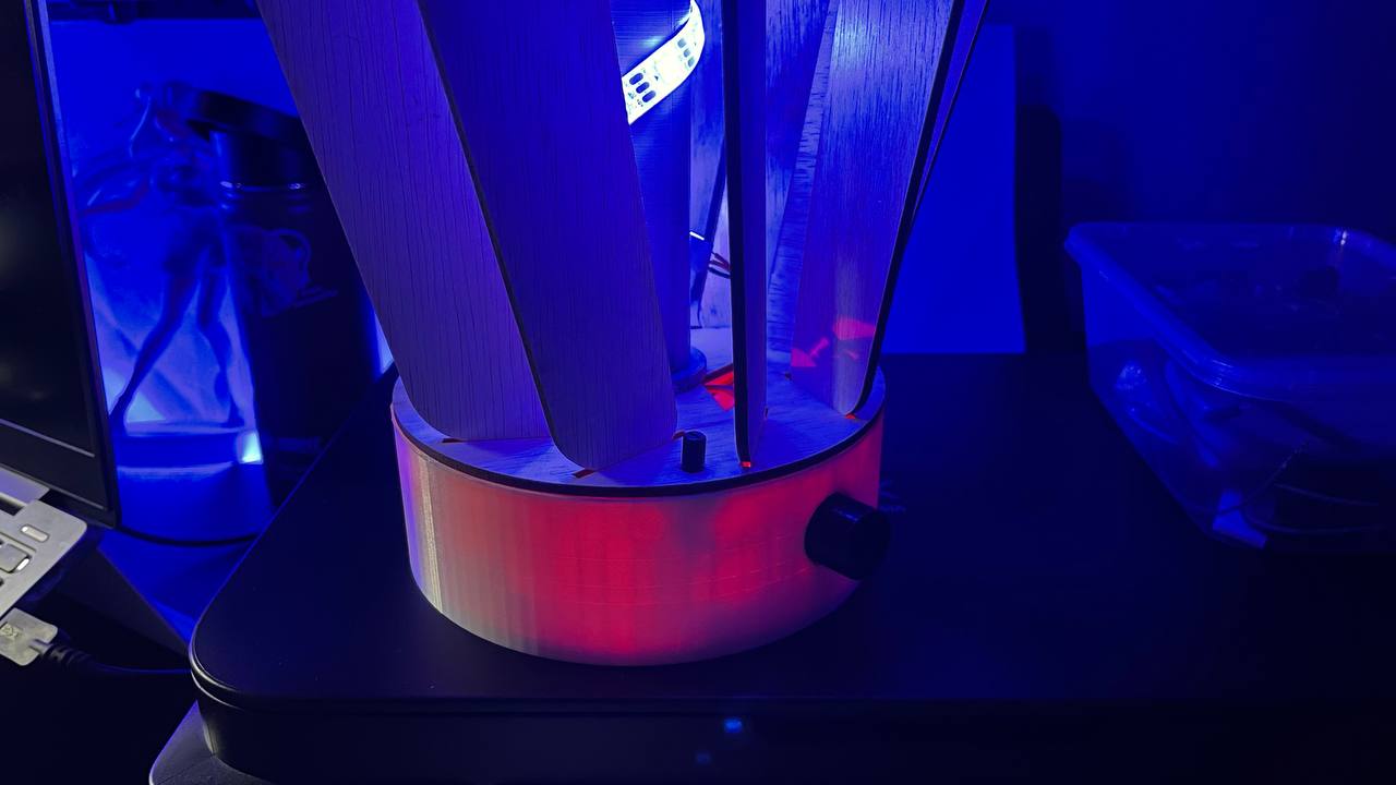
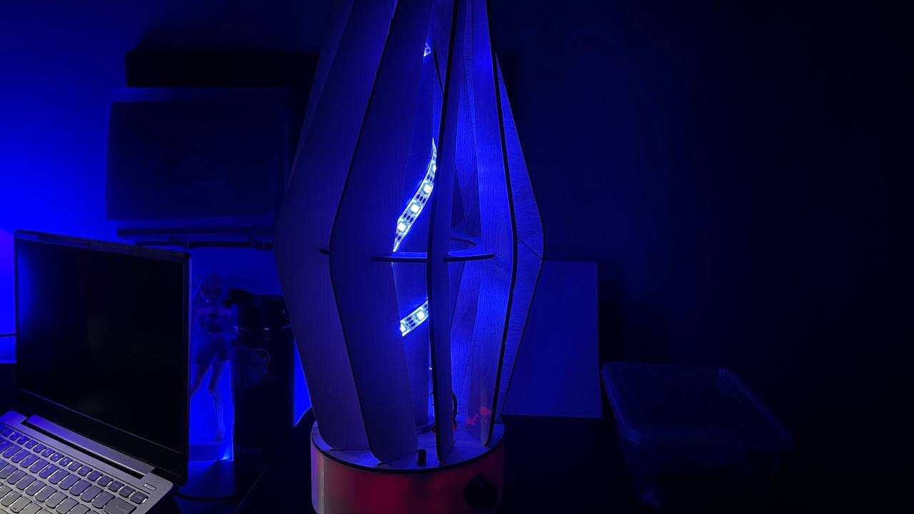
This is the final product, I am first demonstrating the ability of the lamp to change colours. As previously mentioned, the lamp can only display red to blue and any colour in between. I am also demonstrating that the lamp can change its brightness
This is my final 1 min video for the module submission. It has been a great experience taking this module as I had alot of fun. Enjoy!
Part 5: Reflection - Challenges and Possible Improvements
These are the challenges I face during the project
1. Doing the porject last minute and the lab being full during the last 2 weeks, resulted in me having to wait a long time to use the machines. If I had done my work earlier and made the parts over the weeks I would not have had to face this issue.
2. I did not think of my design thoroughly enough so I had to make my own modifications.
3. The top fin snapped a s it was really thin and I had to glue it back together. Next time I could be more gentle or print or cut out a duplicate part that is prone to breaking
These are the possible improvements I could have made to the project
1. The arduino has a red led which makes the base glow red. If I were to improve it, I would line the inside of the base with black paper or something opaque.
2. The leds are directly exposed, which gives of a very harsh glow. If I were to improve it, I would use some kind of material like baking paper or tracing paper and wrap it around the rod to diffuse the light